There can be no doubt that the Hale Telescope is a complex machine that was built to do a simple purpose: collect star light and focus it to a camera.
Of course the telescope has to be complex given the fact that it must point to various locations across the sky and then smoothly move to counteract Earth’s rotation. The physical structure was built knowing that its massive steel parts would sag under the weight of gravity. This was done in such a way as to keep the optical elements precisely aligned.
The glass mirror is also subject to the stresses and strains of gravity. Its surface is very precisely shaped into the form of elliptic parabaloid (the three dimensional form of a parabola). As the telescope points to various directions in the sky the mirror needs to be supported from its underside to counteract any distortion caused by gravity. These distortions can cause the mirror to deform, losing its perfect shape. Without a properly working system of support mechanisms it can become impossible to uniformly focus the telescope.
The designers of the telescope knew this. That is why the mirror was cast with a waffle-like underside.

This is what the mirror looks like when it is stripped of its reflective aluminum coating. The underside clearly comes into view. There are two main features you can see in the glass from this view.
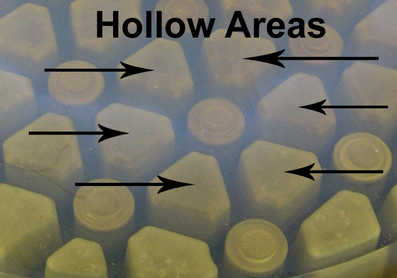
There are 78 hollow areas on the mirror’s underside. Together they make the mirror weigh 42% less than it would if it had been cast with a solid backside. Having a waffle-like backside also helps with the issue of changes in temperature. They give the mirror more surface area, which means that the whole thing can adjust to temperature swings more rapidly.
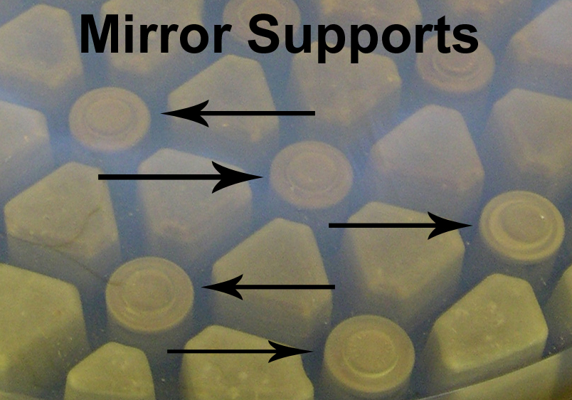 The 36 mirror supports are located in the round areas of the mirror’s underside. The locations of the ones visible in the photo are marked in the image above.
Fitting into each of these round holes is a very complex mechanism that ideally keeps the mirror in a perfect shape.
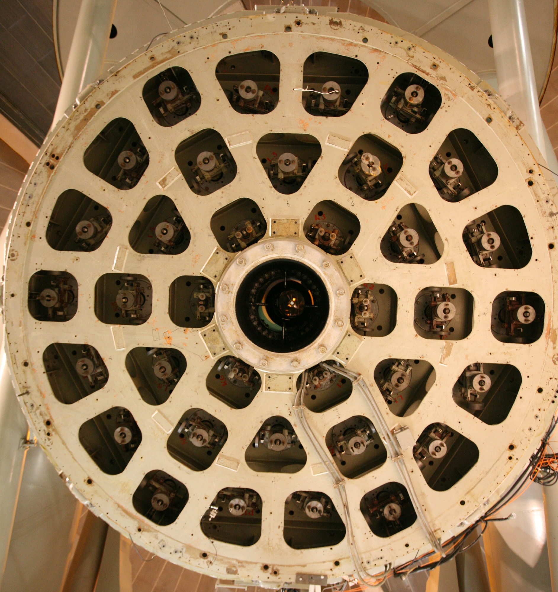
Let’s change the view now and look at the mirror’s underside. This image was taken last week as our current engineering run was just getting started. Notice the hole in the middle. Yes, the mirror has a big hole in it. This allows us to focus light to the underside of the telescope. In the photo of the mirror near the top of this post the hole was plugged.
In concentric circles centered around the central hole you can see the Hale Telescope’s 36 mirror supports. Click to enlarge and you’ll likely notice that the supports do not all look the same. Yes, each of the 36 supports is unique.
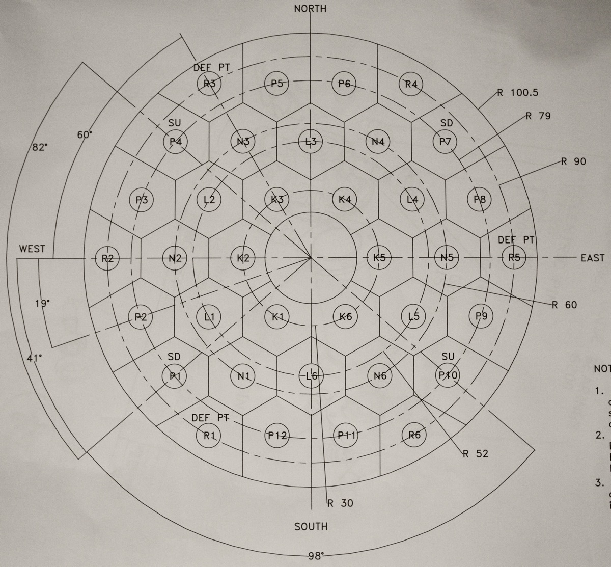
For those who might care, here is a map of the supports. It is in the same orientation as the photo above.
So what exactly do the supports do? They push back on the glass to counteract gravity. The supports near the center hole each exert an average force of about 700 pounds. Out along the outside of the mirror the mirror is thicker and the supports are farther apart, each of the supports needs to push with a force up to about 1,100 pounds.
The forces that the supports need to exert on the mirror must change as the telescope is pointed to different locations on the sky. Take for example the start of the night. The telescope starts off pointing at the zenith and after a quick check of the focus it is time to point at the first object of study. As the telescope moves each of the supports pivots in several ways changing their push on the glass. None of this is actually controlled. Once the supports are in the proper adjustment, gravity does all the work. Newer telescopes have computer-controlled systems that actually push and pull on the base of their mirrors to keep them finely tuned. This is called active optics (not to be confused with adaptive optics which is a different thing).
In 1949 when all the adjustments were done on the 200-inch mirror’s supports Ira Bowen and Bruce Rule found that things were just a little bit off. They added four spring scales to finish their work. Their locations are marked on the map above in positions labeled SU or SD. SU is where a spring pulls up and SD is a spring that pulls down. At mirror support P10 (lower right) the spring scale pulls up with a force of 5 ounces. At P1 (lower left) it pulls down with a force of 21 ounces. At P4 (upper left) it pulls up with a force of 16 ounces and at P7 (upper right) it pulls down with a force of 30 ounces. Remove just one spring scale and the telescope is out of adjustment.

The adjustments finished in 1949 worked for decades, but the mirror supports have to endure some extreme conditions. Every time the mirror is pulled to be washed and realuminized the mirror, the mirror cell and the back supports are potentially exposed to water from the washing. Further, the back supports are exposed to a partial vacuum, which can cause problems with the grease in the bearings.
The supports and the bearings have been worked on before and for the current engineering run 35 of the supports are being worked on (one was done last November).
So what are they doing in this engineering run? I will discuss that in a future post.


2 comments:
The whole telescope housing must rotate to point at different parts of the sky. What is the support system of the housing and what horsepower (electric?) motor is used to rotate the housing?
Yes, the telescope moves to look at different parts of the sky. A 1 HP motor moves the telescope north/south and a 3 HP motor moves it east/west. Tracking to keep up with Earth's rotation is accomplished by a 1/12 HP motor.
Post a Comment